

Emulating a PlayStation controller with a microcontroller
Why should keyboard & mouse gaming be limited to PC only?
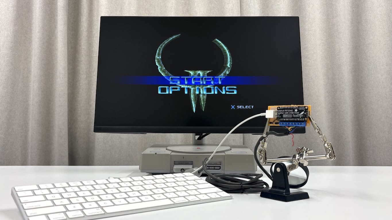
The vast majority of PlayStation players cut their teeth on the now iconic DualShock controller, but did you know the PlayStation also had other types of controllers than game pads?
I happened to come across a PlayStation mouse at an online auction site, and bought it. It’s a neat novelty item. Only select games support it; the list isn’t too long, but it had a few games that stood out to me.
Among the compatible titles was Quake II. Quake is a first-person shooter by id Software. It was a smash hit on the PC and porting it to the PlayStation was a minor miracle.
The PlayStation port is good, especially considering the limited hardware. It plays all right with an analog controller, but the PlayStation mouse beats the DualShock hands down; Quake II was developed for the PC after all.
But why should keyboard and mouse gaming be limited to PC only?
A loony idea
After acquiring the PlayStation mouse, it dawned upon me that I really ought to build a keyboard to pair with it. The premise is simple: Make a keyboard emulate a PlayStation controller. Instead of sending letters it sends key presses such as square, cross, and triangle. That shouldn’t be too difficult, since the dated hardware has been reverse engineered many times over.
Make the keyboard emulate a PlayStation controller. Instead of sending letters it sends key presses such as square, cross, and triangle.
During my preliminary research I came across many of projects that interfaced a PlayStation controller with a microcontroller. Very few did the opposite – emulating a controller. I did still stumble upon some valuable resources1,2,3,4,5.
My goal was to have the device be powered directly by the controller port. It should also be able to support an off-the-shelf keyboard without any modifications. The three main challenges would be: power, interfacing with an USB keyboard, and communicating with the PlayStation.
The first choice to tackle is what microcontroller to use. To permit the use of unmodified keyboards, the board would have to speak USB6. It’s possible to buy host controller chips, such as the MAX3421 to do that with almost any microcontroller, but there are also many low-effort development boards with built-in USB host support.
USB works by an asymmetric protocol wherein devices talk to a single host (usually the computer). Thus, it’s not enough for the board to merely have an USB port (virtually all beginner-friendly boards have one); the USB port has to be addressable so that it can act as an USB host controller.
Hardware
For this project, the Adafruit Feather RP2040 with USB Type A Host was a good fit.
The board needs to be supplied with either 5V through USB-C, or slightly less from a LiPO battery. Neither suits our needs; the PlayStation supplies ~3.3V and ~7.5V on two of the controllers wires7. Luckily Adafruit mentions on their page some alternative options:
“It is not recommended, but technically possible [to] … Connect an external 5V power supply to the USB and GND pins.”.
The reason Adafruit doesn’t recommend this is that plugging in external power while having the board connected to a computer could fry the computer. We don’t need to have both plugged in simultaneously, so we’ll disregard the warning.8

Although keyboards don’t usually consume much current, the power supply needs to be able to supply both the board and the USB port. I used a proper Pololu 5v, 500ma step-down voltage regulator to step down the 7.5V to the needed 5V.
To communicate with the PlayStation, I tore up an existing controller and connected its wiring harness to the Feather board. The PlayStation DualShock exposes 9 wires. We use 7 of those (data, acknowledge, command, clock, attention, and additionally power and ground).
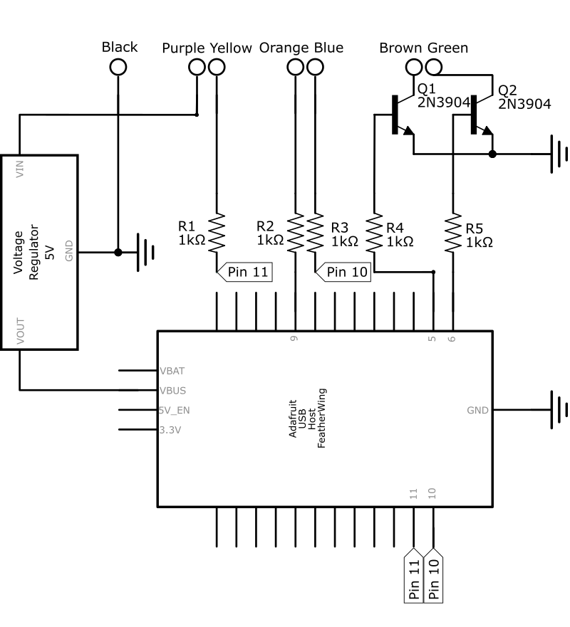
The PlayStation communicates with the controllers over a (slightly modified) SPI bus9. Thus, our controller needs to drive the data and acknowledge lines (brown and green wires), the rest are dictated by the PlayStation.
I decided to go for bit-banging the protocol on GPIO pins. Both data and acknowledge lines are in an open collector configuration, so we need transistors for switching them10. Two NPN transistors will do.
In an open collector configuration, the emitter of the transistor is connected to ground, and the collector (output) can be pulled low by turning on the transistors (Q1, Q2 in the schematic below). The PlayStation has internal pull-up resistors for pulling the lines high.
I also added some protective resistors (R1-R3) on the signal lines in case I accidentally set them high, but in hindsight these could be removed. The schematic is straight forward:
Laying out the components on stripboard presented a fun challenge as I wanted the circuit board to be small. Fritzing is a great tool for iterating different layouts. A key realization was that, since the Feather board sits raised on headers, some components could be placed beneath it. This cut the final size to about 71 x 33mm (2.8 x 1.3”).
After prototyping on breadboard and using Fritzing, I began soldering. The wire colors follow those of the PlayStation to prevent mistakes.
As you might see in figure 2, many wires had to pass the headers on the copper side of the circuit board.

Software
The easiest way to send data over the wire is by bit-banging the GPIO pins according to the given protocol10. First, our code waits for the attention line to drop, indicating that the console wants to communicate with the controller. After that, we wait in a loop for the clock pulse to fall, and then –- simultaneously –- read and write a single bit on the the command and data lines respectively. When a byte has been transmitted (LSB first), we pull the acknowledge line down11,2,5,.
One thing to bear in mind is that due to the open collector configuration, a high signal on the GPIO corresponds to a low signal in the output, so the bits have to be inverted.
To read the keyboard, we’ll use the Adafruit TinyUSB library, which uses Pico-PIO-USB for host functionality.
The USB stack also has to be enabled; in the Arduino IDE that’s done via
Tools
USB Stack
.
Since we have to both read the keyboard and write to the PlayStation simultaneously, it makes sense to split out the tasks over the processors two cores.
The cores communicate with each other via a single atomically writable variable called currentButtonState.
What follows is an overview of the main parts of the code.
The details, such as excangeByte are glossed over here.
First, we’ll initialize the two cores and wire the GPIO pins for input and output. The first core is responsible of writing to the PlayStation. The communication is handled by an interrupt handler on the attention line. The second core is occupied with reading the USB keyboard.
// ...

// Setup core 0 for PlayStation communication
void setup() {
  pinMode(PIN_DATA, OUTPUT);
  pinMode(PIN_ACK,  OUTPUT);
  pinMode(PIN_ATT,  INPUT);
  pinMode(PIN_CMD,  INPUT);
  pinMode(PIN_CLK,  INPUT);

  // React to attention line and send controller data
  attachInterrupt(digitalPinToInterrupt(PIN_ATT), onAttFall, FALLING);
}

void loop() {}


// Setup core 1 as USB host
void setup1() {
  rp2040_configure_pio_usb();
  USBHost.begin(1);
}

void loop1() {
  // Read USB and handle callbacks
  USBHost.task();
  LOG_FLUSH();
}

// ...
The USB host library is wired to use named callbacks.
In tuh_hid_mount_cb we setup the keyboard to use the simple boot protocol mode (code omitted).
The boot protocol is a simplified way mice and keyboards can report their state12.
Besides setup, the main callback is tuh_hid_report_received_cb, which is called whenever a HID device (the keyboard) reports activity.
// ...

// An atomic state shared between the cores
volatile uint16_t currentButtonState = 0xFFFF;  // 0xFFFF = no buttons pressed

// USB callback
void tuh_hid_report_received_cb(uint8_t dev_addr, uint8_t instance,
                                uint8_t const* report, uint16_t len) {
  // Accept only callbacks of "boot keyboard" protocol
  bool shouldRead = tuh_hid_interface_protocol(dev_addr, instance) == HID_ITF_PROTOCOL_KEYBOARD
      && len >= 8);

  if (shouldRead) {
    uint16_t newState = 0xFFFF;

    // Read keycodes from report[2-7]
    for (int i = 2; i < 8; i++) {
      uint8_t key = report[i];
      if (key == 0) continue;
      if (key == 0x59) newState &= ~(1u << BIT_LEFT);
      if (key == 0x5A) newState &= ~(1u << BIT_DOWN);
      if (key == 0x5B) newState &= ~(1u << BIT_RIGHT);
      if (key == 0x5D) newState &= ~(1u << BIT_UP);
      // ...
    }
    currentButtonState = newState;
  }

  // Ready to receive next callback
  tuh_hid_receive_report(dev_addr, instance);
}

// ...
Finally, on the first core we read and write the controller protocol based on currentButtonState.
For details on the protocol, see Playstation.txt, Interfacing a PS2 Controller and notes by Digitan.
// ...


// Send and receive data from console.
void onAttFall() {

  uint16_t state = currentButtonState;
  uint16_t response = buildRensponse(state);

  // Send 0xFF and check data is destined to the controller port
  if (exchangeByte(response[0]) != 0x01) return;
  sendAck();

  // Send model number 0x41
  exchangeByte(response[1]); sendAck();

  // Sending data 0x5A
  exchangeByte(response[2]); sendAck();

  // Send actual button data
  exchangeByte(response[3]); sendAck();
  exchangeByte(response[4]);
}
Getting the timing right is important. Originally the controller was intermittently shown as unplugged, but by tuning delays I managed to get the controller to work reliably.
// ...

static inline void sendAck() {
  // Delays like this are important when bit-banging
  delayMicroseconds(6);
  gpio_put(PIN_ACK, 1);
  delayMicroseconds(6);
  gpio_put(PIN_ACK, 0);
}
Another oversight led me to debug the USB side for a good while. By default the PR2040 runs on 133 MHz, but the USB library requires either 120MHz or to 240Mhz. That can be changed in the Arduino IDE via Tools CPU Speed .
Working prototype and next steps
And there you have it. With the circuit and code in place, it works. In theory, it should also work on a PlayStation 2, since the controllers are cross compatible.

I’m happy with how this version turned out. Placing some components beneath the Feather board made the layout compact. Soldering still requires more practice, but this was a good stepping stone. A custom PCB could cut the size further – perhaps something for the future.
Meanwhile, here’s a demonstration:
My plan is to improve the circuit and build a keyboard (and case) that’s on brand with the PlayStation. That’ll be another post.
Thanks for reading.
-
Interfacing a PS2 Controller by Scott Driscoll. ↩ ↩2
-
Playstation.txt, Joshua Walker, 2000. ↩
-
Sony PlayStation controller information by Andrew J McCubbin, 1998 (archived). ↩
-
PlayStation Controller Interpreter circuit, 2005 (archived). ↩ ↩2
-
In some special cases, it’s possible to trick an USB keyboard to fall back to PS/2 protocol and read key presses without a dedicated USB host controller. ↩
-
PlayStation specifications by Martin Korth (along with a superior mirror). ↩
-
Adafruit Feather RP2040 with USB Type A Host reference documents. ↩
-
After sending a byte (in standard SPI fashion) the controller must pull the acknowledge line low. ↩
-
I later realized that hardware level SPI is supported by the board – I might use that in a later version. ↩ ↩2
-
Except for the last byte. ↩
-
USB Human Interface Devices at osdev.org. ↩